Valve-ball Forging
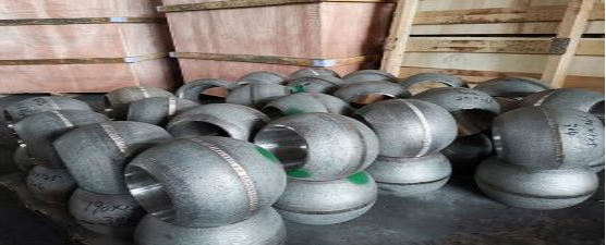
Valve Ball Forging Classification: Forging Classification: mainly divided into free forging and die forging.
1.Free Forging
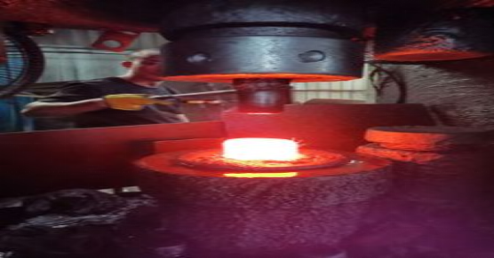
Free forging is to place the heated metal billet between the top and bottom of the forging equipment to exert impact.
A process in which a blank is directly plastic deformed by force or pressure, thereby obtaining the required forgings.
Classification: manual free forging, hammer free forging, hydraulic press free forging;
Advantages: strong applicability, great flexibility, short cycle and the only method for large forgings;
Disadvantages: low precision, large machining allowance, low efficiency and high labor intensity
2.Die Forging

Die forging is called mold forging. It is formed by placing the heated blank in a mold in the forging equipment.
1.2.1 Die forging equipment: In industrial production, hammer up die forging is mostly used;
1.2.1.1 Steam-air hammer, tonnage ranging from 5KN to 300KN (0.5 ~ 30t);
1.2.1.2 Hot die forging press commonly used for die forging on pressure machine, with tonnage ranging from 25000KN to 63000KN;
3.Forging Ratio
Forging ratio: The ratio of the cross-sectional area of the metal billet before and after forging. The calculation method of forging ratio is different for different forging process.
When drawing, the forging ratio is Y=F0/ F1 or Y =L1/ L0
F0, L0 — the cross-sectional area and length of the ingot or billet before drawing;
F1, L0 — the cross-sectional area and length of the ingot or billet after drawing;
Forging ratio during upsetting, also called upsetting ratio or compression ratio, whose value is Y=F1/ F0 or Y=H0/ H1
F0, H0 — the cross-sectional area and height of the ingot or billet before upsetting;
F1, H1 – Cross sectional area and height of steel ingot or billet after upsetting.
4.Forging Temperature

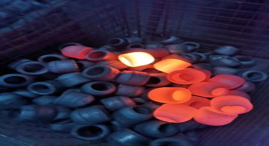
1.4.1 Initial forging temperature: The initial forging temperature shall be understood as the maximum allowable heating temperature of steel or alloy in the furnace;
1.4.2 Final forging temperature: the steel shall remain sufficiently plastic before the end of forging, and the forgings shall obtain recrystallization structure after forging;
1.4.3 Forging temperature of common materials (℃, for reference only):
| Material | Initial Forging Temp. (C) | Finish Forging Temp. (C) |
| F304 | 1130 | 850 |
| F304L | 1130 | 850 |
| F316 | 1200 | 850 |
| F316L | 1200 | 850 |
| F6A | 1150 | 750 |
| F51 | 1200 | 900 |
| F53 | 1200 | 900 |
| F55 | 1200 | 900 |
| 17-4PH | 1200 | 900 |
| A105 | 1200 | 800 |
| LF2 | 1200 | 800 |
| A105 | 1200 | 800 |
| 4130 | 1180 | 800 |
| 4140 | 1150 | 850 |

Heat Treatment
Heat treatment system of commonly used materials:
1 Carbon steel material: A105
1.1 Heat treatment system: normalizing and air cooling.
1.2 Metallographic structure general structure: pearlite + ferrite structure
2 Low Temperature carbon steel material: LF2
2.1 Heat treatment system: quenching + tempering (tempering) (water cooling + air cooling).
2.2 General structure of metallographic structure: Sostenite structure
3 4130, 4140 low alloy steel
3.1 Heat treatment system: quenching + tempering (oil cooling + air cooling).
3.2 General structure of metallographic structure: Soxhlet structure
4 Martensitic stainless steel: F6a
4.1 Heat treatment system: quenching + tempering (or two tempering) (oil or air cooling + air cooling).
4.2 General structure of metallographic structure: Sostenuto structure
4.3 Description: F6a is divided into four grades, which are controlled by tempering temperature to ensure that the mechanical properties of the corresponding grade are reached.
5 Austenitic stainless steel material: F316/ F316L/ F304 / F304L/ F321….
5.1 Heat treatment system: solid solution treatment (water cooling).
5.2 General structure of metallographic structure: austenite structure
6 Duplex stainless steel: F51/ F53/ F55….
6.1 Heat treatment system: solid solution treatment (water cooling).
6.2 General structure of metallographic Structure: Austenite + ferrite structure (about half)